TECHNOLOGY
This is a repository for open source electrophysiology hardware building and data analysis software used by and/or designed in the Katz Lab.
For any questions, or for further details, please contact Joseph Wachutka or Narendra Mukherjee.
Electrophysiology Recording System
We use the RHD2000 family of electrophysiology hardware/software from Intan Technologies. The Intan software and electrophysiology data recording is run/stored on a PC running the Ubuntu operating system. This PC interfaces with a Raspberry Pi 3 running Ubuntu Mate to delivery time-locked experimental information to the RHD2000 interface board via digital input/output channels on the two hardwares.
Electrophysiology Processing and Data Analysis
Data from our RHD2000 system is stored on a local storage server here at Brandeis University, and analysis is run on the Jetstream Cloud hosted by Indiana University.
Micro-drive Design and Construction
Download .stl files below in order to 3D print the body of the micro-drive. We use Sketchup to design and edit our designs, but there are many free softwares out there for 3D design and editing (files attached at bottom of page).
3D print the top and bottom piece for the micro-drive.
We use a FormLabs Form 2 printer and the print quality is very good.
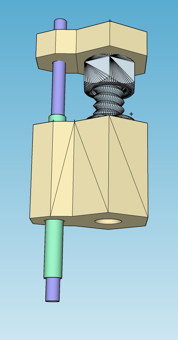
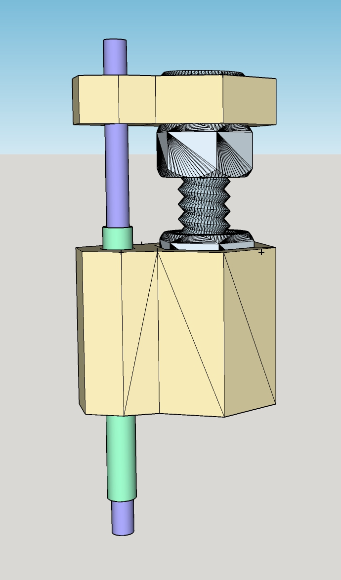
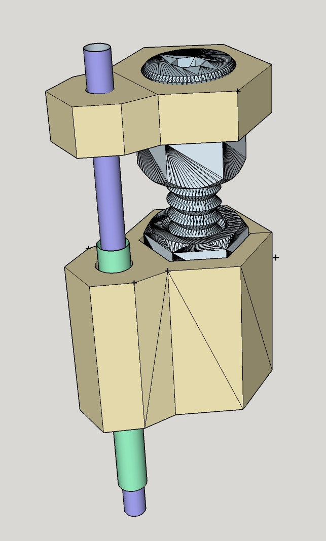
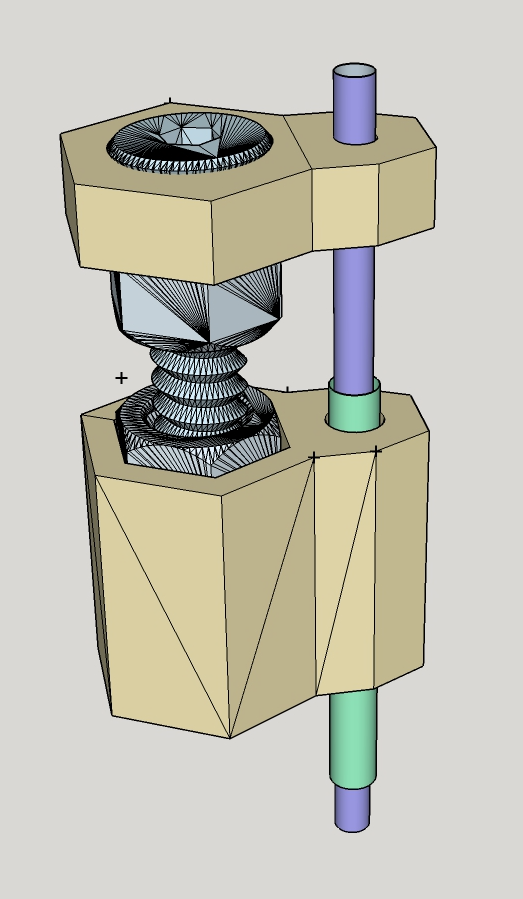
Glue 1.2M nut into hex recession on 3D printed base piece.
Place Screw through 3D printed top piece, place nut on screw and tighten until snug (but not tight) against the top piece. Glue or solder the nut to the screw in this position, holding the top piece snug between the top of the screw and the nut.
Insert the screw into the nut glued into base piece and lower until screw is through the nut.
Cut the inner cannula (shown in light purple) tube to 20mm in length (this cannula will house the electrode wire).
Cut the outer cannula (shown in green) to 12mm in length, and insert into bottom piece as shown. Glue in place.
Insert the inner cannula through small hole in top piece as shown, and through outer cannula. Glue in place to top piece.
The inner cannula should now move up and down through the outer cannula as you rotate the screw.
The length and gauge of these cannulas should be adjusted based on size/number of electrode wires and depth of target implant location.
Use a caliper to measure the distance of travel per rotation (the screw and nut piece listed here moves 0.25mm per rotation of the screw
Electrode Design and Construction
Cut wire into 16 strands of the same length. Wire length depends on the design of the electrode, we cut our wires to ~15-20cm in length for the design described here.
Bundle these 16 wires together and glue the bottom 5cm of the wire with a liquid glue (this helps for feeding the wire through the micro-drive later).
Take the top (non-glued) portion of the wires and separate the individual wires. Feed each wire through a holes on the green board (listed in supplies below, SFC attachment shows design of green board)
Repeat the first 3 steps for the other row on the green board, for a total of 32 wires.
Remove insulation from the tips of the wires that are contacting the green board using a small razor.
Place Omnetics connector (listed in supplies) on top of the green board contacts.
Solder the Omnetics connector to the green board so that one wire is in electrical contact each leg of the Omnetics connector.
Trim excess plastic from green board, arms have been added to the design to facilitate building.
Place the bottom end of the 32 wires (in 2 bundles of 16) through 4cm length of heat-shrink tubing (listed in supplies), slide the tubing as far up the wire as possible and apply heat
Place the bottom end of the 32 wires through the inner cannula on the micro-drive (design explained above)
When enough wire has been fed through the inner cannula so that the heat-shrink tubing comes in contact with the top of the micro-drive, glue the end of the heat-shrink tubing to the micro-drive (be careful not the get glue on the screw).
Cut the wire that exits the bottom of the inner cannula to length (we use ~3mm exposed wire length).
Test connectivity of the wire prior to usage.
Cost Estimation
Micro-Drive
3D printed components $0.15
Screw $0.05
Nuts (x2) $0.03
Cannulas (x2) $0.50
Glue $0.10Total micro-drive cost ~$0.83
Electrode
Wire $10.45
Green Board $ 1.50
Solder $ 0.25
Glue $ 0.25
Omnetics Connector $35.00
Total electrode cost ~$47.45
Supplies List
Electrophysiology Recording System
RHD2000 Evaluation Board: Intan Link
RHD2132 Headstage Amplifier Boards: Intan Link
Pricing for these Intan products can be found here: Intan Link
Ubuntu operating system for data storage/electrophysiology data collection and analysis: Free Download Link
Experimental/Behavioral Control System
Raspberry Pi 2 or Raspberry Pi 3 boards will work for experimental control: Raspberry Pi Website
Raspberry PI 3: Amazon Link
Ubuntu Mate operating system for Raspberry Pi: Free Download Link
Microdrive Supplies
Screws for Katz Lab microdrive: Amazon Link
Nuts for Katz Lab microdrive: Amazon Link
Heat-shrink tubing for covering exposed electrode wire: Amazon Link
32-channel + fiber optotrode outer cannula (0.042" OD, 0.032" ID): Amazon Link
32-channel + fiber optotrode inner cannula (0.028" OD, 0.0215" ID): Amazon Link
32-channel electrode outer cannula (0.03575" OD, 0.02775" ID): Amazon Link
32-channel electrode inner cannula (0.025" OD, 0.019" ID): Amazon Link
16-channel mouse outer cannula (0.032" OD, 0.023" ID): Amazon Link
16-channel mouse inner cannula (0.02" OD, 0.016" ID): Amazon Link
Custom designed plastic drive parts are 3D printed using a FormLabs Form-2 printer. (.stl files attached below, 3 sizes)
Electrode Supplies
Nichrome/Formvar electrode wire (either 0.001" or 0.0015" coated diameter): A-M Systems
32-channel Omnetics connector: Part Number A79026-001, Specs Sheet, Pricing
Green Boards used to connect microwires to 32-channel Omnetics connector: Custom made by SF Circuits (.pdf file of our design is attached below.)
Low-temp solder paste: Amazon Link